ESP8266-01S Wi-Fi Module
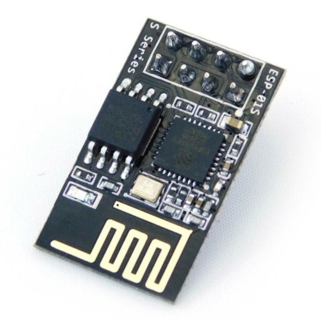
The ESP8266-01S WiFi Module is a compact, low-cost WiFi solution designed for Internet of Things (IoT) projects. Whether used as an access point or a station, this module enables seamless internet connectivity, making it an excellent choice for smart devices and home automation systems. Its versatile features allow developers to integrate WiFi capabilities into their projects using AT commands, Arduino IDE, or Lua scripting.
Key Features:
- Built-in TCP/IP protocol stack
- 802.11 b/g/n Wi-Fi support
- Low power consumption
- Integrated 32-bit MCU
- Programmable GPIO pins
- AT command support
Technical Specifications:
- Power Supply: 3.3V (max input: 3.7V)
- Current Consumption: 100mA (in operation)
- I/O Voltage: 3.6V (max)
- I/O Source Current: 12mA (max)
- MCU: 32-bit low-power processor @ 80MHz
- Flash Memory: 512kB
- WiFi Standards: 802.11 b/g/n
- Deep Sleep Mode: <10uA power consumption
- GPIO Pins: 2 (can be hacked to support up to 4)
Applications:
- Home automation systems
- Wireless sensor networks
- IoT data logging devices
- Remote control applications
- Wi-Fi-enabled consumer electronics
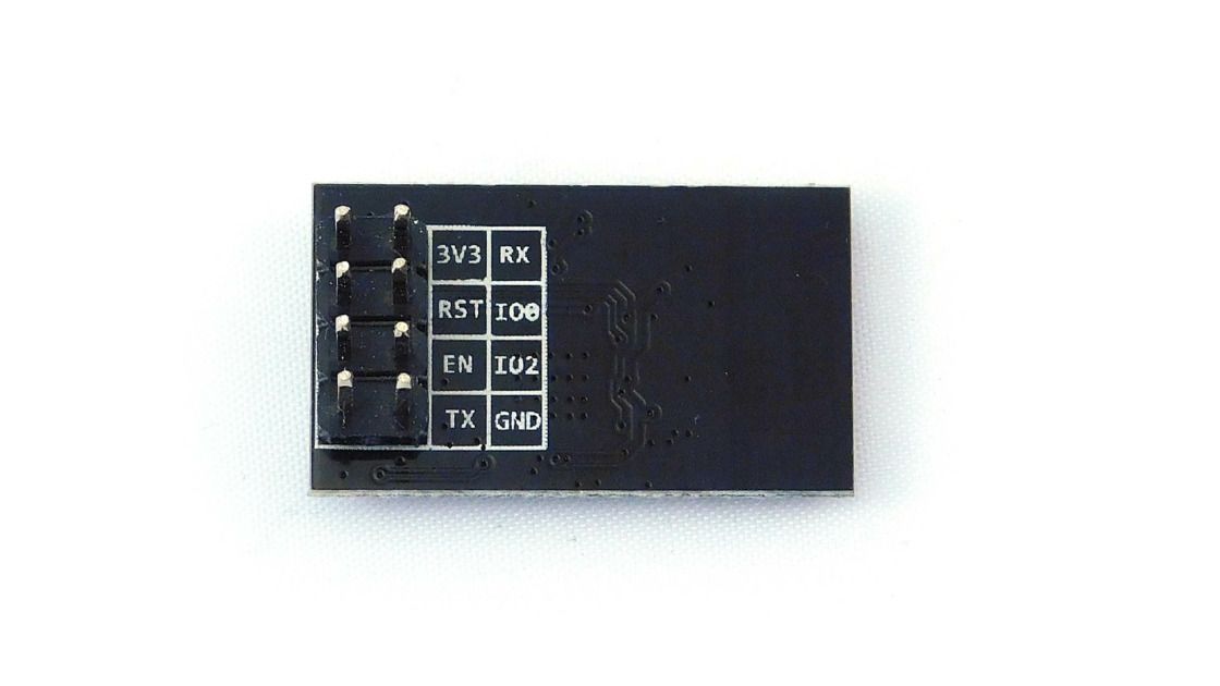
Pinout Diagram:
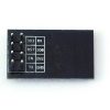
Here is the pinout for the ESP8266-01S module:
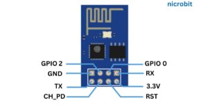
Pinout Configuration:
| Pin Number | Pin Name | Alternate Name | Normal Use | Alternate Use |
|---|---|---|---|---|
| 1 | Ground | – | Connected to the ground of the circuit | – |
| 2 | TX | GPIO-1 | Connected to RX of programmer/uC | It can be used as a general-purpose I/O |
| 3 | GPIO-2 | – | General Purpose I/O pin | – |
| 4 | CH_EN | – | Chip Enable (Active High) | – |
| 5 | GPIO-0 | Flash | General Purpose I/O | Serial programming mode when held low |
| 6 | Reset | – | Resets the module | – |
| 7 | RX | GPIO-3 | Connected to TX pin of programmer/uC | It can be used as a general-purpose I/O |
| 8 | VCC | – | Connect to +3.3V | – |
Usage:
Wiring Connections:
- Power: Connect VCC to 3.3V and Ground to the circuit ground.
- Programming: Connect TX to the RX of your microcontroller and RX to the TX for serial communication.
- CH_EN: Ensure the CH_EN pin is connected to 3.3V for normal operation.
- Connect RST to VCC (or to a reset circuit if needed)
Boot Modes:
- Flash Mode: GPIO-0 High, GPIO-2 High – Runs the uploaded program.
- UART Mode: GPIO-0 Low, GPIO-2 High – Enters programming mode for code uploads via serial communication.
Sample Code (Arduino IDE):
#include <ESP8266WiFi.h>

void setup() {
  Serial.begin(115200);
  WiFi.begin("YourSSID", "YourPassword");

  while (WiFi.status() != WL_CONNECTED) {
    delay(500);
    Serial.print(".");
  }

  Serial.println("");
  Serial.println("WiFi connected");
  Serial.println(WiFi.localIP());
}

void loop() {
  // Your code here
}
Operational Guidelines:
- Power up the module
- Programming Mode: Hold GPIO-0 low during startup to enter programming mode. This allows uploading code through the Arduino IDE or any other serial communication tool.
- Normal Operation: Release the GPIO-0 after uploading the code to run the program.
- Initialize the Wi-Fi connection using appropriate library functions
- Wait for the connection to establish
- Perform desired Wi-Fi operations (e.g., send/receive data)
- Handle any disconnections or errors
Caution:
- Always ensure the module is powered with 3.3V, exceeding this can damage the module.
- Be cautious of power consumption during programming; the module may require more current. Use an L1117T regulator to maintain stable power delivery.
- Avoid exposing the module to static electricity
- Do not exceed maximum ratings for GPIO pins
- Implement proper heat dissipation in enclosed designs
- Avoid exposure to moisture or extreme temperatures to ensure long-term functionality.
Troubleshooting Tips:
- Issue: The module is not responding to commands.
Solution: Ensure the CH_EN pin is connected to 3.3V and the module receives adequate power. - Issue: Unable to upload code.
Solution: Verify that GPIO-0 is held low during startup to enter programming mode. - Issue: Unstable WiFi connection.
Solution: Check your power supply and confirm you are within WiFi range. - Issue: Module resets during operation.
Solution: Ensure the power supply is stable, and use a proper voltage regulator if necessary. - Issue: High temperature during operation.
Solution: Ensure proper ventilation and avoid overvoltage conditions.
Common Questions and Answers
- Can I use the ESP8266-01S with 5V logic?
No, it requires 3.3V logic, and exceeding this may damage the module. - How do I enter programming mode?
Hold GPIO-0 low during startup to enter UART programming mode. - What is the maximum current draw of the module?
The module consumes around 100mA during operation, so ensure your power supply can provide at least 500mA. - Can the ESP8266-01S be used as an Access Point?
Yes, it supports both Access Point and Station modes. - Is it compatible with the Arduino IDE?
Yes, the ESP8266-01S can be programmed using the Arduino IDE. - How many GPIO pins does it have? The ESP8266-01S has 2 usable GPIO pins (GPIO-0 and GPIO-2).


Reviews
There are no reviews yet.